Circuits
LOGIC and CIRCUIT DESIGN
From Found. of C.S., Aho and Ullman
Ch. 13 (Reserve) and
On Line.
- High and Low voltage levels encode true and false (1 and 0).
- Circuit design shares many principles with algorithm design --
modularity, divide and conquer methods.
- Circuits are often parallel: simpler ``data model'' than a
programming language.
- Costs: Number of gates (surface area), depth, fan-in, fan-out,
(packaging).
CONCEPTS
Gates (primitive circuits for logic operations)
-
Gates organized into circuits.
-
Combinatorial circuits: equivalent to logical expressions.
- Karnaugh Maps for minimizing circuit size: charming "Victorian"
graphic technique: can't imagine it's practical nowadays but it's
instructive.
- Practicalities like physics and timing properties.
- Adders: ripple-carry and divide-and-conquer.
-
Circuits with memory (unlike combinatorial ones).
GATES
Each one does a Boolean function:
AND, OR, NOT, NOT-AND (NAND), NOT-OR (NOR).
Number of Boolean Functions on n inputs: 2^{2^n}, from
boring (e.g. constant) to universal (e.g. NAND, NOR).
A B AND NAND OR NOR
0 0 0 1 0 1
0 1 0 1 1 0
1 0 0 1 1 0
1 1 1 0 1 0
In the literature we write + for OR, use 'multiplication'
for AND, and the macron (overbar) for NOT. In HTML there's no way to
put any accents over most letters, so I'm stuck with using
x' for NOT(x).
e.g.: x + ( x'y' )+ (yz).
Build other functions out of gates:
x ⇒ y is
x' + y.
GATE SYMBOLS
CIRCUITS
Combinatorial (gate's output cannot reach its input -- no cycles in
gate-connection graph.)
Opposite is Sequential, which correspond directly (in a
formal, provable sense) to
deterministic finite automata.
The circuit's output is 1 for an input
if and only if automaton accepts corresponding
input.
E.g. of combinatorial circuit to compute
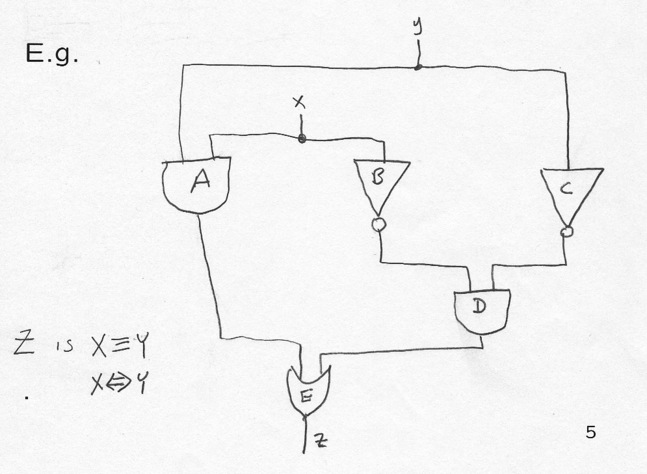
Z = X ≡ Y
SEQUENTIAL CIRCUIT EXAMPLE
LOGIC TO CIRCUIT
Given Logic expression: using Structural Induction
(very FOCSy!): Circuit will be a tree (as expected).
Consider the expression as a tree (say fully parenthesized).
Basis: if expression tree is a single node, the expression
can only be an input, say x, and the circuit is this input itself.
Induction Otherwise the expression has a logical operator
θ
at
the root and has a number of subtrees Ei
for θ's arguments.
LOGIC TO CIRCUIT CONTINUED
Our inductive hypothesis applies to the subexpressions (subtrees), so
there is a circuit C_i for each E_i. To build the circuit, take a
gate for operator θ and give it n inputs, one from each of
the
C_i in order, and the output for this new circuit is the output of
the θ-gate.
Note this is a super-literal approach to circuit design that doesn't
notice shared subexpressions or other simplifying transformations.
CIRCUIT TO LOGIC
Know circuit must be a tree, so we can pick a topological order of its
nodes
(gates) such that if the output of the ith gate in the order feeds
an input of the jth gate in the order, then i < j. (see
Topological Sort, a three-line algorithm that uses DFS and
inserts nodes into a list sorted by depth -- first textbook example of an
important DFS algorithm). A topological sort is an ordering of
vertices in a directed acyclic graph, such that if there is a path
from u to v, then v appears after u in the ordering. No cycles; start
with vertex with no incoming edges; output it, remove it and its
edges,
repeat.
Two of many Topological Orders: A B C D E, C B D A E
CIRCUIT TO LOGIC CONTINUED
Induction again, this time on variable i in the statement S(i):
For the first i gates in the topological order, there are logical
expressions for the output of these gates.
Basis: at i=0, nothing to prove, done.
Induction: for ith gate in order, say inputs are
I1, ...,
Ik. If Ij
is a circuit input, say x, then let the expression
Ej for input
Ij be x.
If Ij is output of some other gate,
that gate must precede i in the order, so its expression has already
been constructed. Let operator associated with gate i be θ.
Then expression for gate i is θ(E1,
..., Ek), or for
strictly binary operators could write (E1)
θ (E2).
ONE-BIT ADDER: Continuing Exampls
KARNAUGH MAPS 1
Sum of Products Expressions (Disjunctive normal form)
From truth-table to minterms, sum (OR) of which
is what we want.
One-bit adder TT
x y c d z d minterms (1 if each
var matches row values)
0 0 0 0 0
0 0 1 0 1
0 1 0 0 1
0 1 1 1 0 x'yc
1 0 0 0 1
1 0 1 1 0 xy'c
1 1 0 1 0 xyc'
1 1 1 1 1 xyc
Take sum (OR) of minterms of rows with value 1. This expression
is 1 when inputs match one of rows for which function is 1.
x'yc +
xy'c +
xyc' +
xyc. That's the DNF for the boolean function d.
KARNAUGH MAPS 2
KMs find sum-of-product expressions for Boolean functions, tend to be
simple (efficient) solutions.
KM is n dimensional tabular form for n-argument Boolean function:
practical up to n=4.
Note if we have two minterms differing by one variable's negation, can
forget (delete, pitch) that variable!
(pq + p'q) ≡ q. This is the idea behind creating bigger
implicants.
q(p+p') ≡ q(TRUE) ≡ q .
IMPLICANTS
An implicant for Boolean function f is a product x of
literals for which no assignment of values to the variables of f
makes x true and f false. Thus, by prop logic (!)
if the implicant is true
the function is true.
For example, every minterm for which the function
f has value 1 is an implicant of f.
An implicant covers the points for which it has value 1. So
a logical expression for a Boolean function could be the OR of a set
of implicants that together cover all points where function value is 1.
A prime implicant for f is one with as few literals as
possible: it ceases to be an implicant for f if any literal is
deleted. That is, if we double its size it will cover a point with
value 0.
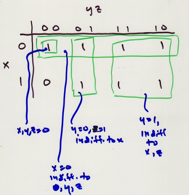
2-D KARNAUGH MAP E.G.
2-D KARNAUGH MAPS
A rectangle corresponding to an implicant can either be a single point,
(corresponding to a minterm). OR a row or column (corresponding to pair
of points that agree in one variable and disagree in the other). This
reduces to the single variable they both share. OR the entire map,
in which case the product reduces to the constant 1, and
function is TRUE, which has 1's at every point.
The bigger the rectangle, the fewer literals in the product.
We generally like fewer literals, which means fewer operators, which
means simpler. So we might want to consider only prime implicants to
cover a map.
WHY KARNAUGH MAPS? 1
WHY KARNAUGH MAPS? 2
3-D KARNAUGH MAPS 1
Map the cube onto 2-D in such a way that adjacent columns correspond
to assignments of truth values that differ in only one variable.
Also columns ``wrap around.'' The carry-out function looks like
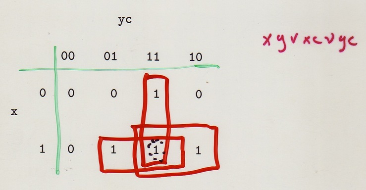
3-D KARNAUGH MAPS 2
Which rectangles can represent implicants? Must be product of
literals. In a product, variable appears negated, not negated, or not
at all. When it appears (negated or not) it cuts in half the number
of points in corresponding implicant So number of points always a
power of 2.
Each permissible implicant is collection of points that, for each
variable, either includes only points with that variable equal to 0,
or includes only points with that variable equal to 1, or does not
discriminate on the basis of that variable.
So in 3-D we get 1) any point; 2) any column; 3) any pair of
horizontally adjacent points, including wrap-arounds in cols 1,4;
4) any row; 5) any 2 x 2 square of 2 adjacent cols, including
wrap-arounds; 6) the entire map.
PRIME IMPLICANTS 1
Prime implicants are really the point of the Karnaugh Map: they are
the shortest way to represent a chunk of the truth table.
PRIME IMPLICANTS 2
PRIME IMPLICANTS 3
Below also a 4-D Karnaugh Map.
4-D KARNAUGH MAPS
Do the 2-variable trick on rows as well. Use same row order for
pairs as col. order in 3-D for same reason. Define both row and
col. adjacency with wrap-arounds. NOTE implication: 4 corner points
are a 2 x 2 rectangle!
Rectangles corresp. to products of literals: 1) Any point; 2) Any two
horiz. or vert. adj. points, including wrap-arounds; 3) any row;
4) any column; 5) any 2x2 square including wrap-arounds; 6) any 2
x 4 or 4 x 2 rectangle, including wrap-arounds (like
first and last cols); 7) entire map.
LOGIC FROM KARNAUGH MAP
To get the product of literals that is TRUE
for just the points in an implicant rectangle,
let p be any variable.
- If every point in rectangle has p = 1, p is a literal in
product.
- a If every point in rectangle has p = 0, p' is a literal in product.
- Otherwise, some points have p=0 and some p=1, and the product
does not contain a literal with variable p.
LOGIC FROM KARNAUGH MAP: EG
ONE BIT ADDER
Multiple inputs and outputs. Inputs x and y: two bits at some
pos. in binary number, and c, the carry-in bit from position to
right. Output: sum bit z (1 if an odd number of x,y,c are 1) and
the carry-out bit d (1 if two or more of x,y,c are 1).
x y c d z d
0 0 0 0 0
0 0 1 0 1
0 1 0 0 1
0 1 1 1 0 yc
1 0 0 0 1
1 0 1 1 0 xc
1 1 0 1 0 xy ⇒ yc ∨ xy ∨ xc
1 1 1 1 1 xyc
ONE BIT ADDER -- KARNAUGH MAP
ONE BIT ADDER -- CIRCUIT FROM LOGIC
Turns out this is a really bad and brainless idea, but it is
clearly possible.
Just implement the truth-table for the one-bit adder: expect both
z and d to be the ORs of ANDs and you'd expect
to have to deal with seven or eight cases, one per row of the table.
Create the NOT versions of all inputs with inverters, then create AND
gates for each minterm needed in any output. Number gates 1-7 (000
not needed) and think of labels as binary for the xyc inputs, 0 for
negated. OR the needed minterms together, one OR for each output.
LOGIC FROM CIRCUIT
For interest's sake, going the other way is easy.
Getting the logic from the circuit means selecting a topological
order: what is natural and works is NOTs, ANDs, ORs. Clearly
NOT of x is x'. The output of gate 1 by definition is
x'y'c, etc. The output of the OR gate for z is thus
x'y'c + x'yc' + x y'c' + xyc
And for d:
x'yc + xy'c + xyc' + xyc,
Which you can prove is same as the KM expression (how?):
yc + xc + xy.
PHYSICAL CIRCUIT CONSTRAINTS
Gate delay and circuit speed: speed goes with the number of gates on
the
longest path in the circuit: analgous to program running
time. Technology dictates absolute time.
Dollar cost about proportional to number of gates. Circuits on large
areas need longer wires, get more propagation delay. Also
imperfections are more likely with larger areas.
Large fan-in and fan-out (inputs and outputs) slow down a gate in
practice.
So circuits can be optimized over several criteria.
TWO CIRCUITS FOR "OR"
DIVIDE AND CONQUER ADDER
Algorithm design techniques affect circuits, too ("basic ideas
keep cropping up"...CB).
Could build an adder for integers from the one-bit, delay-3 example
adder. It's not bad design (can get delay two if we do all
complementing outside). This gives a ripple-carry adder. So
delay of 3n for n bit integer add.
OR Design n/2-bit adder, use two of them with some glue to build
adder. Easy to see how to build D and C OR circuit, no? Analysis needs
recurrences,
which you learn about elsewhere (maybe 172?).
BAD IDEA
The glue is a problem for the adder. This won't work:
NEXT IDEA: N-ADDER SPECS
Let the left half adder compute two answers, one each for 0 and 1
carry-in. When RH completes, know which answer to choose.
In fact delay for n is 3 + 2*delay(n/2) and that means total delay
is
3(1 + log n). For n=32 this is 18, not 96 for ripple-carry.
We want n inputs xi, same for yi
inputs. Outputs are:
- si, i.e. s1,s2,...,
sn, n-bit sum (w/o carry-out) assuming no
carry into the rightmost place.
- ti, similar but with a carry-in.
- carry-propagate bit p = 1 if carry-out to
left, assuming carry-in from right.
- carry-generate bit g = 1 if carry-out even if no carry-in.
Note g ⇒ p but (g,p) = (0,1) is OK: (0101 + 1010).
RECURSIVE CONSTRUCTION
If n=1, have two inputs x,y, need to compute s,t,p,g -- these
are
governed by the logic:
s = x y' + x'y
t = xy + x' y'
g = xy
p = x + y
(As usual, work thru cases to see these are right).
s: 0 t: 1 g: - p: 1
x x x x
y y y y
----- --- ---- -----
1 1 1- 1-
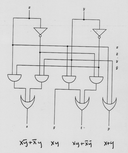
BASE CASE ONE-BIT ADDER (1-ADDER)
INDUCTION
Here's our plan for the D and C adder: the FIX circuit must:
- compute
the carry-propagate and generate bits for the 2n adder
-
Adjust the left half of the s's and t's depending on a carry into
left from right or not.
FIX IN DETAIL
If carry into R of entire 2n adder circuit. They'll be carry out at
left end if either
- Both halves propagate a carry: pLpR is true: also includes R
half generating carry and L half propagating. gR ⇒ pR,
so
(pLpR + pLgR) ≡ pL pR.
- L half generates carry: gL true.
Thus p for the 2n adder is p = gL + pLpR.
If no carry in on R, get carry-out at L if either
- R half generates a carry that L propagates
- L half generates a carry. Thus
g = gL + pLgR.
S's and T's
R half bits unchanged from output of R n-adder since L half doesn't
influence it. So sn+i = siR,
tn+i = tiR.
See Next Diagram!
Pick a case depending on g:
L half depends on how R can generate carry. If no carry in from R end
of 2n adder, this is what the si are supposed to cover. Any
carry-in must have been generated in R. Thus if gR is true, then
si = tiL, since that's the situation we pay the t's to
cover. And if gR is false, si = siL. So
si = siLg'R + tiLgR.
Pick a case depending on p:
If carry-in at R half. What about t's on L? A carry into L if R
propagates one (pR = 1). So ti takes its value from tiL if
pR is true, and from siL if pR is false.
FIX SUMMARY
Inside FIX we have circuits (depth at most 3, it turns out) for
p = gL + pLpR.
g = gL + pLgR.
si = siLg'R + tiLgR, for all i
ti = siLp'R + tiLpR, for all i
E.g. for ti:
ADDER DELAYS
D and C Adder:
Super-simple recurrence: Base-case 1-adder has delay 3, so does the
FIX.
D(1) = 3
D(2n) = D(n) + 3.
So D(1) = 3, D(2) = 6, D(4) = 9, D(8) = 12...
D(n) = 3(1+ log n).
Ripple Adder:
D(n) = O(n).
D and C ADDER GATE COUNT: PICTURE
D and C ADDER GATE COUNT: MATH
G(1) = 9 by counting, then G(2n) = 2G(n) plus FIX gates. FIX can
invert gR and pR, then needs 2 ANDs and an OR for each of the
n si's and ti's, and we need 2 gates each to compute g and
p. So FIX needs 6n+6.
G(1) = 9
G(2n) = 2G(n) +6n + 6
This goes like 1:9, 2:30, 4: 78: 8: 186 or in general G(n) = 3n log
n + 15n -6. And fewer if pick n to be nice number say 32: can simplify the right
half at all levels. Note ripple-carry adder uses fewer gates (less
than half
as many
for n=32). Also gates grow faster (by log) in D and C. But speed
so much better D and C is practical choice.
MEMORY
If load= 0: a is 1, c is 0. If d is 1,
b is 1, so d remains 1. But if output of d
is 0, then b is 0, so output of d remains 0 while
load = 0. So circuit output stays ``what it was'' as long
as load
stays 0.
If load=1, a, b go to 0. Output of c will
be whatever in is. And also output of d will be
whatever c is, which is what in is. So changing
load to 1 sets output to whatever in is. Changing
load back to zero lets this value circulate between
b, d.
SUMMARY
- Gates and relation to Logic
- Gates combined into Circuits
- Combinatorial and Sequential Circuits
- Circuits from Logic, Logic from Circuits
- Karnaugh Maps
- Divide and Conquer for Adder (Text has MUX too).
- Circuit Practicalities, Speed and Size
- Memory