Start: Monday, April 13, 2020 Due: Friday, April 17, 2020. Email writeup to Prof RC, and post a video of your robot in motion to the FB Constructors Group
So now you have your chassis. With servos and wheels attached. The next goal is to make your robot move. To do this, you need to position and attach the other major components (batteries, breadboard, Arduino), wire them together with auxiliary components (LEDS, resistors etc.), and write a program to demonstrate some sort of controlled movement.
First, you need to attach your two battery boxes, breadboard, and Arduino Uno to your chassis. You need to consider positions. In particular, it is very helpful if the Arduino and the breadboard can be connected using the 6" jumpers and ribbon cables included in the kit.
Don't glue or do anything else permanent that would make removing the components difficult or damaging. I recommend velcro tape for the breadboard. The battery units can be attached with the same velcro tape, or friction-fit into carefully made slots/boxes in the chassis.
The Arduino is slightly trickier because of the pins protruding from the underside. You can probably stick velcro tape over these. A better solution is to use the included #2 screws to attach the arduino to a card made of double-laminated mat-board. Here you need to be careful not to damage the pins or warp/crack the circuit board by forcing them against the substrate. If you can find or make some spacers to go around the screws between the circuit board and the substrate, that is one approach.
Another method is to use your icepick to punch holes for all the pins to go into. This requires a template, which you can make by pressing the Arduino into sheet of ordinary paper on some cushioned surface, (or with your fingers) so that the pins poke holes in it. This paper can then be taped down to the substrate and used to guide your icepick work.
The image below shows an example of wiring on the breadboard. I am not expecting you to copy this exactly. You've got to work out your wiring. The picture is just to give an idea of how to go about it. Note use of ganged ribbon cables (pins glued together) to connect the Arduino. These make the connections easier to trace and less likely to wiggle loose.
Note also the doubled power and ground line from the battery boxes, again for connection robustness. I recommend using the power rail on one side of the breadboard for the Arduino power, and the one on the other side for the motors. THE POWER LINES FOR THE ARDUINO AND THE MOTORS MUST BE KEPT SEPARATE. Otherwise, the current surges associated with starting up the motors will occasionally drop the voltage enough to cause the Arduino to reset. Which is very annoying. The grounds, on the other hand, must be connected to each other and to the Arduino ground.
Finally, note the use of the short "flat" jumpers for wiring on the circuit board itself.
This is more compact, more secure, and easier to trace/analyze than using loose 6" jumpers.
Once you have the placement of resistors, LEDs and any other components set, they can be
cut down so they lie flat or in contact with the board as well rather than sticking up
where they are easily dislodged.
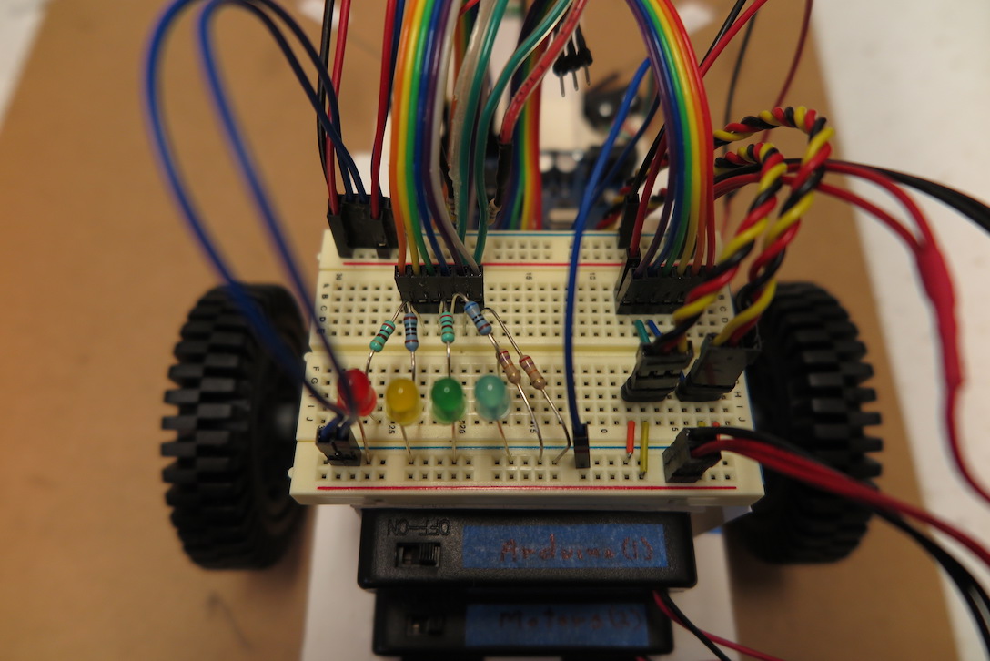
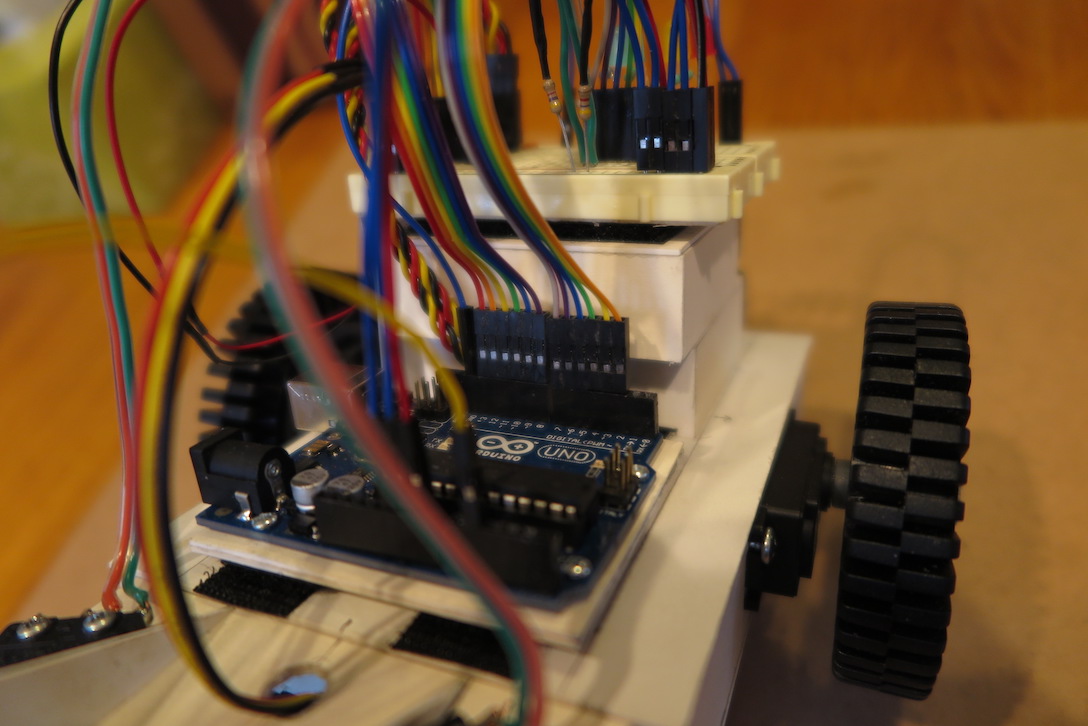
Image showing use of ganged ribbon jumpers on the Arduino. Again, I am not suggesting
you copy this exactly, just illustrating a useful strategy.
The boilerplate demo I had you study is a good place to start. The code references whisker switches, and the piezoelectric speaker, so it won't run as is without those components installed (though you may have the second shipment by now). But it can be easily adapted to run through a simple sequence at power-up. I suggest you do adapt it, both to get used to modifying the boilerplate and to gain deeper understanding of how it works. You will have to adapt the code significantly when it comes time to implement more interesting behaviors (next week) so get used to it.
The ports used are simply suggestions. You are free to change them. The combination used here was selected to facilitate use of ganged ribbon jumpers, but it is not the only such arrangement.
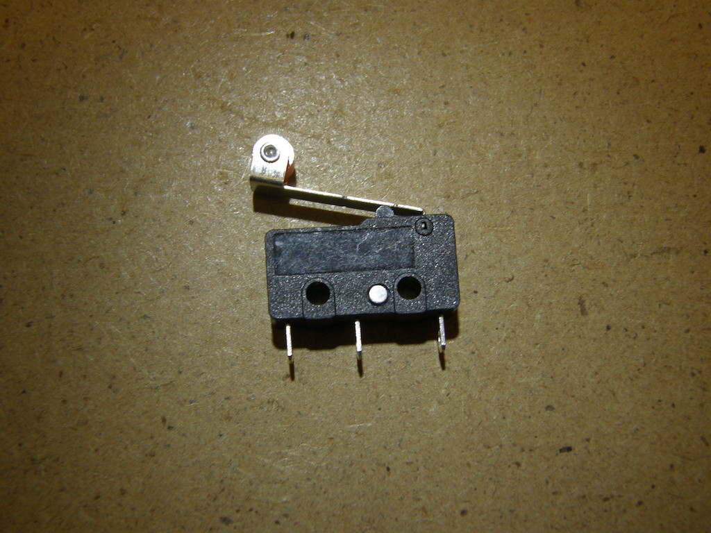
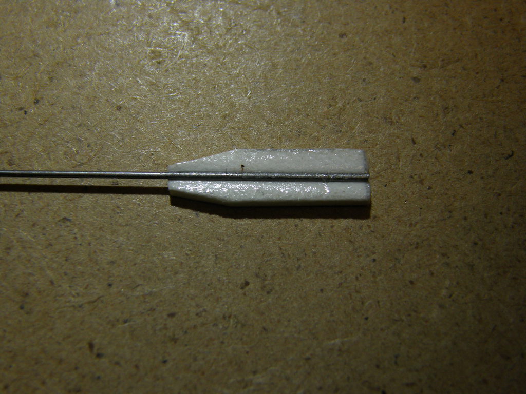
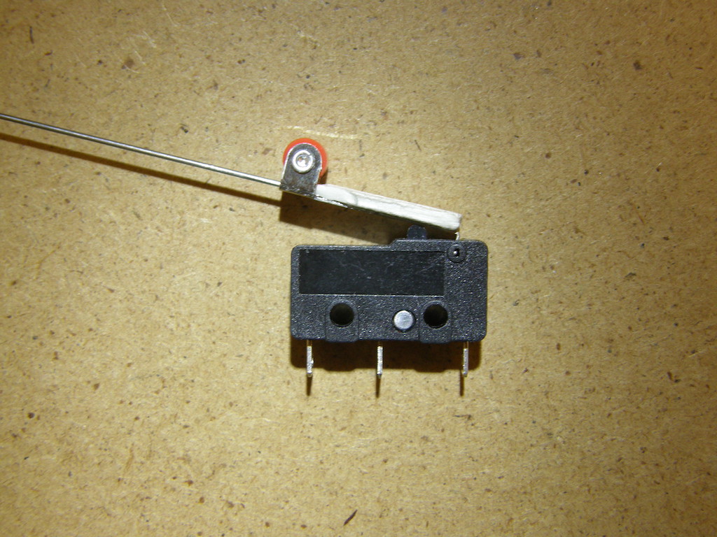
If you want to install whisker switches at this stage, the pics below show how to attach
the piano-wire whisker to the mini-switch. Basically, you press the wire firmly into a small strip or matboard(using pliers, a hammer, or your full weight on a hard object) creating a groove into which the wire is set with a tiny bit of superglue.
The wire is then inserted under the roller, and secured by supergluing
the matboard strip to the switch lever.
You should roughen the metal strip with a bit of sandpaper or emory or a
small file to increase the adhesion of the glue.
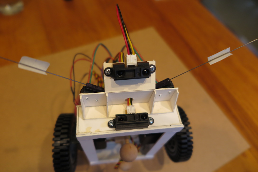
Finally, if you want to install IR distance sensors, the image below shows one possibility. Here, the long-range sensor is looking outward. It can be used to detect obstacles dead ahead, and/or if the robot is rotated, to generate a full-sweep array providing information about the environment all around the bot. The short-range sensor is pointed down and ahead at 45 degrees. This configuration can be used to detect a drop-off so the bot can run on a table (or around stairs) and not fall over the edge and break itself.
